Note that this angle value must not exceed 90º. This builds a relationship between the constraints.
Prezentaciya Na Temu Copyright Dassault Systemes Assembly Design Advanced Catia Training Foils Version 5 Release 8 January 2002 Edu Cat E Asm Af V5r8 Skachat Besplatno I Bez Registracii
Iterative and Collaborative Design Loop Abaqus for CATIA V5 is an effective tool for deploying proven analysis workflows across the enterprise.

. For example a user makes in Catia a Paste Special As Result With Link on the one part in another in the SmarTeam tree Catia Design symbol appears between the two parts. Within CATIAs sketching work bench any parallel lines picked for dimensioning will create a linear dimension. You can either select the geometry or the command first.
Since this thread has had such a high number of reads I wanted to share this information on Links and Design in Context for everyone to read. The problem was submitted on. This is one of the many problems I have encountered.
Ceci définit les règles des opérations des objets liés tout au long dune opérationcomme un résultat dune opération effectuée sur un objet spécifique. It enables advanced simulation capabilities to be used routinely by design engineers to accelerate and improve product development. The code has been enhanced problem conclusion.
Again that still clutters the sketch with extra dims. That several features are equal not that thy just happen to have the same value at this. These concepts are the counterpart on the programming side of what the end users sees and manipulates on the screen.
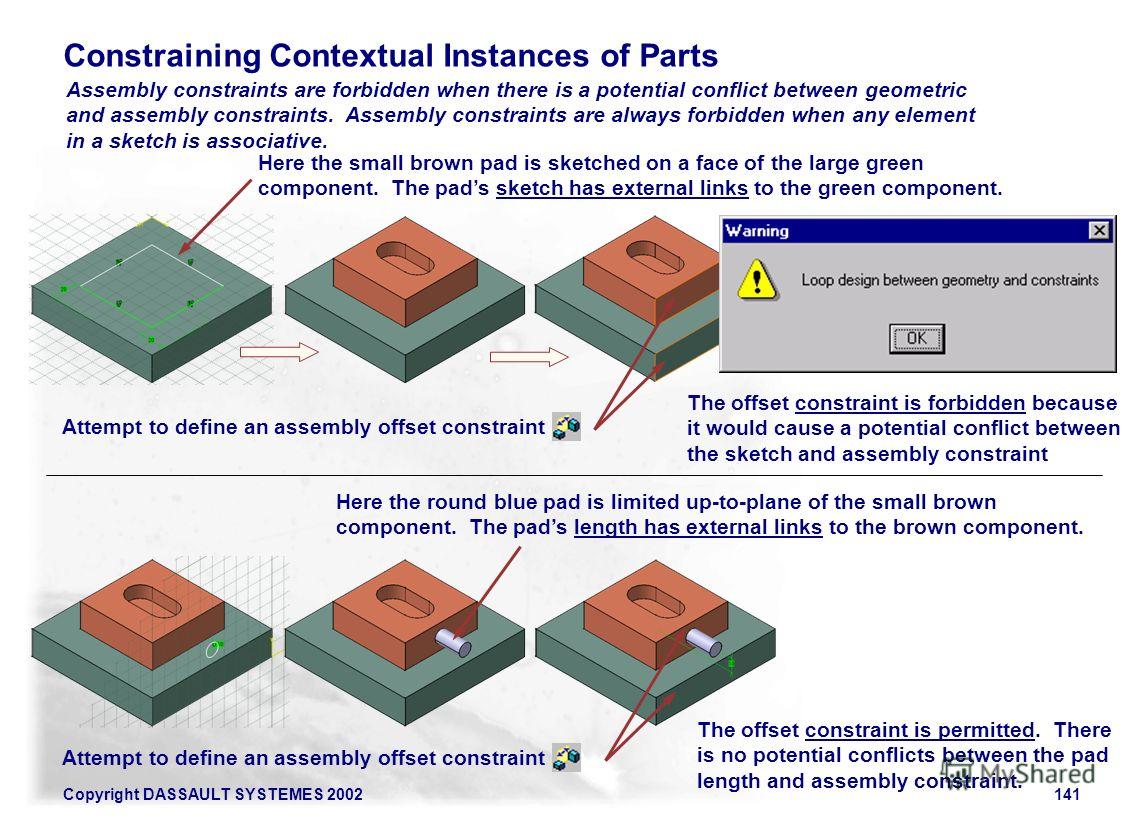
Loop design between geometry and constraints the constraint network should be solved. I am new to Catia V5 and in the process of creating a parametric assembly. Parallelism angle value equals zero Perpendicularity angle value equals 90º When setting an angle constraint you will have to define an angle value.
Catia version 5 release 9. THIS PROBLEM IS PERMANENT RESTRICTION IN CATIA When updating the product an error message Loop Design is displayed. Ferdo posted the following link in the CATIA Forum on Eng-Tips.
Sketcher constraints - No equal. Loop design between geometry and. THIS PROBLEM IS PERMANENT RESTRICTION IN CATIA The creation of a coincidence constraint between 2 elements holes from Plate_New and Plate_For_Dist parts is refused due to a loop design between this constraint and geometry on which this constraint lies it means geometrical definition of Plate_For_Dist.
Loop design between geometry and constraints 4. This is normal as there is a loop design between the constraint to update and geometry on which it lies contextual part. The constraint has been created on a level where a bug should allow this creation.
This video explains ways to use fixed geometric constraint in catia sketcher. This constraint can be created between either two elements. The parallelism constraint appears in the specification tree at the same level as the child components and they are displayed in the geometry.
Start the Sketch Module in Catia V5. Angle type constraints fall into three categories. In the same way a constraint can not be created.
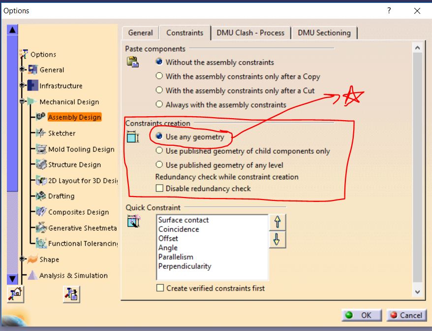
The best way to overcome a design loop is not to make reference to any geometry but to define constraints parameters using the other parts parameters you will create an external parameter Rajendra Mathad. Publish command help to reflect same operation to number of part model where as u can apply operation individually to open in new window from right click on the particular part. A warning window opens.
These constraints are in priority. Aardvarkdw Mechanical 30 Oct 08 1033. Click Coincidence Constraint icon in Constraints toolbar then select Line1 in Part1 and Line1 in Part2.
This is Part 2 of a 5-part article that appeared in the CATIA Operators Exchange COE newsletter back in 2005. Creates a parallelism constraint between these two planes. Create a linear dimensional constraint between the vertical line and V-Axis as shown in Figure 11.
I would rather have a sketch that clearly shows my design intent ie. For make constraints geometry you can simply select product from specification tree and than apply existing component from insert menu than constrain it with update. Any non-parallel lines will create an angular dimension.
Parallelism geometric constraint in catia sketcher. This video explains ways to create geometric constraint in catia sketcher. Leverage familiar CATIA design environment and methods.
The following table shows the elements you can select. Select the Constraint Contact icon from the Constraint toolbar Constraint Creation subtoolbar for giving Contact Constraint. Place the dimension as shown in Figure 10 Step 12.
Parallelism geometric constraint in catia sketcher. This video explains regarding usage of length geometric constraint in catia sketcher. Loop design between geometry and constraints local fix.

Analyzing And Resolving Over Constrained Or Inconsistent Sketches

Geometric Constraints Catia Youtube
What Does This Error Message Mean During Constrain Attempt Dassault Catia Products Eng Tips
Do We Need To Publish Geometry Every Time While Using Assembly Design In Catia V5 Grabcad Questions

About Assembly Constraints
Examples Illustrating Three Types Of Loops A Two Holes On Multiple Download Scientific Diagram

About Assembly Constraints

About Assembly Constraints
0 komentar
Posting Komentar